MiSeq Control Electronics
I recently wrote about the MiSeq cameras on the other substack. I also decided to take a quick look at the control electronics in the Miseq. But I don’t have quite as much to say about this, so you get it here on the second substack!
Paid subscriptions here (and the main substack) will help pay for broken bits of sequencers and are appreciated (I set the subscription here to the lowest allowable value).
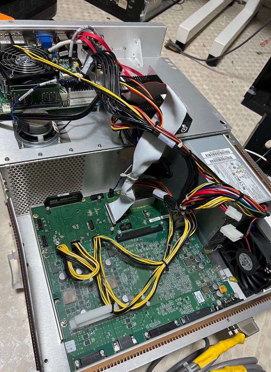
As shown in the image above, most of the MiSeq electronics (aside from the cameras and a few other bits like the RFID reader) sits in the same box and the compute.
It’s connected to the main compute board via a long ribbon cable. This appears to be a serial interface (based on the PCB silk screen).
The control electronics sit on a couple of PCBs in mezzanine configuration. The top PCB looks like this:
The two identical layouts to the top are the LED drivers (Red and Green). Below this we have connectors that head out to various sensors around the device and two connectors for driving TECs (Peltier devices).
The TECs appear to have some pretty beefy associated power electronics… All this is fed from the same ATX power supply that drives the motherboard.
If we remove this we find the lower control PCB:
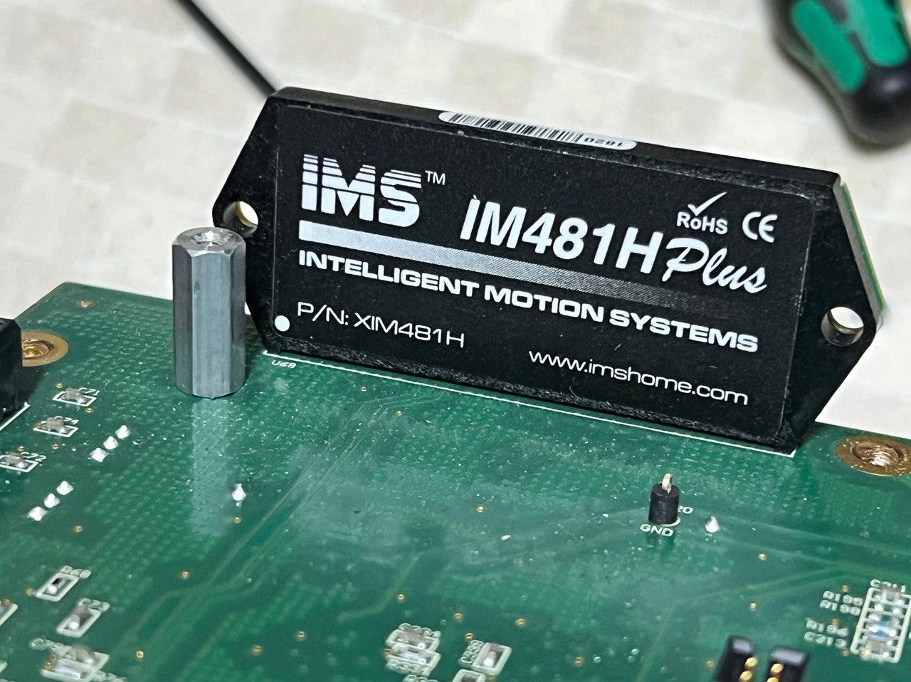
The top side for this is pretty bare. It have ATX power supply connectors, which it loops through to the compute motherboard. There’s a stepper motor driver (which is probably for one of the stages):
There would normally also be a PI piezo driver attached to this board I believe. This would be for the objective focusing module (at some point I will likely to a post on this so you know… subscribe)
Flipping this board over shows some more interesting components:
There’s old our friend the Spartan 6 (LX45)! To be honest, I doubt this is doing anything that probably couldn’t be handled by a DSP or microcontroller. As previously mentioned there are a couple of FPGAs in the cameras already. So the Spartan 6 here doesn’t have to do much heavy lifting.
That’s about it! I can’t see that Illumina have made much of an attempt to cost optimize here. The only consideration in that direction is perhaps the use of a off the shelf PC power supply. But I suspect that was just convenient (given they’re using it to drive a PC motherboard among other things).
The whole thing could be put together much more cheaply if you really wanted to. But when the instrument costs $100K there’s no real motivation to shave a few hundred dollars off the BOM cost!
That’s it for now! There should be some more teardowns coming soon! Including something quite… big… stay tuned!


